The ideal built environment is the seamless merging of architectural, structural and building service elements in a way that is almost magical.
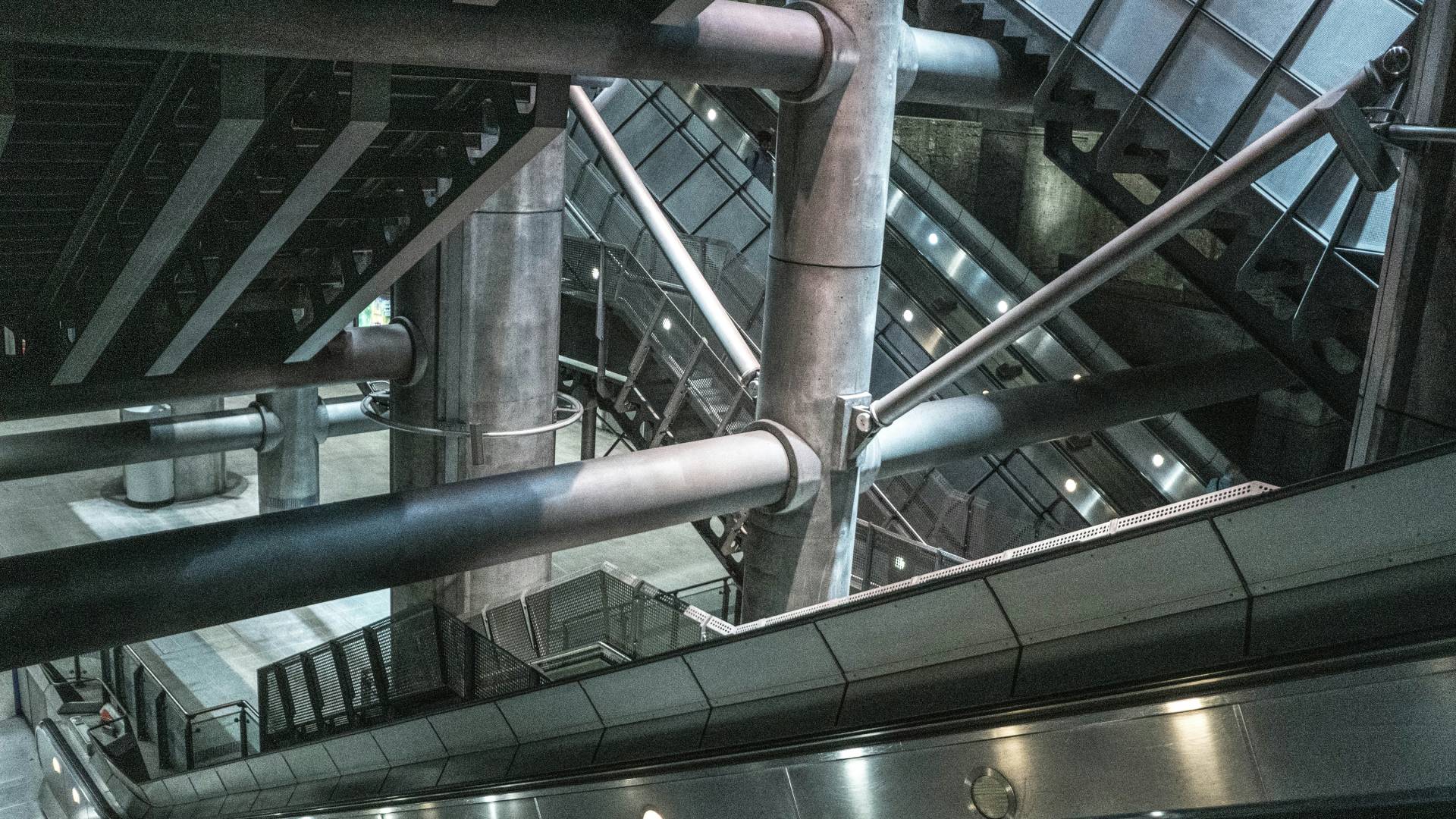
In most commercial multistory buildings, one of the most essential and common components of the building is shafts – the vertical penetrations through slab that allows passage of pipes, ducts and cable trays. Some professionals refer to them as service ducts or shaft ducts, while others refer to them as riser points. Since ducts are defined as HVAC members used in transporting air, it is possible to have a service duct (a structural member) that also doubles as an HVAC duct. In such rare cases for instance, air can be extracted directly through the service duct.
The location and sizing of shafts are key to the proper implementation of building services work and is one of the first activities any services engineer undertakes before starting a project. There are a few things to consider during this activity paramount of which include structural general arrangement, impact on architectural layout, distance from fixtures, and access. It is important to initiate a discussion with the architect on these elements before the concept design even begins.
Placement of shafts must always consider proximity to structural members. One cannot expect to create an opening on top of a beam or too close to a column as this will create unnecessary challenges for the structural engineer. Horizontal building services members such as pipes, HVAC ducts and cable trays may have to pass through or under drop beams to access the shafts. The type of structural system deployed can also dictate shaft placement. For instance, a flat slab system will always provide more options for horizontal runs than a beam-slab system due to the dropped beams in the latter.
Care must be taken as well not to adversely affect the architectural vision. For instance, placing a shaft in a location that changes the building facade. Corners, parts of cabinetry, along hallways, or any other discreet location are always best. The architect always has final decision on shaft placement. However, size is determined by the services engineer.
As much as possible, shafts should be centralized so that they are not so far away from fixtures/equipment they serve. This is more critical with sanitary systems. Drainage pipes are sloped thus the further fixtures are from shafts, the more likely it would be that pipe runs would drop too low and either cause clashes or fall below the ceiling line.
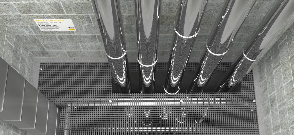
Finally, the question of access to building services members in shafts must be addressed. For most shafts, access is only required for isolators (valves and switches). Provide access only when necessary and such that their opening doesn’t affect the operation of other fixtures or equipment. If possible, the entire shaft should be made of easily removal panels to allow access to the entire section. Typically, however, full access is only necessary during extensive renovations.
A well-designed shaft arrangement seamlessly blends into the architectural scheme while providing the functionality required of it. When it comes to shafts, less is more, and that is where the magic is.